-
Collaborate on structured 3D models in visionOS
Learn how to bring structured 3D models to life in visionOS. We'll cover USDZ preparation, show you how to manipulate individual entities within hierarchical assemblies, and inspect the internal components within a model with a cross-sectional plane. Create stunning exploded-view animations for design review and collaboration experiences on Apple Vision Pro.
Chapters
- 0:00 - Introduction
- 2:55 - Asset preparation
- 5:05 - Manipulating the hierarchy
- 8:15 - Interactive clipping
- 18:16 - Autoexpansion
- 24:10 - Next steps
Resources
Related Videos
WWDC26
WWDC25
- Better together: SwiftUI and RealityKit
- Share visionOS experiences with nearby people
- What’s new in RealityKit
WWDC24
-
Search this video…
Welcome to Collaborate on Structured 3D Models in visionOS. I'm Bill. Today I am going to talk about building spatial experiences on Apple Vision Pro. Specifically, how to work with complex assemblies and multi-dimensional data in ways that simply aren't possible on a flat screen.
Let's start with a look at what that can feel like.
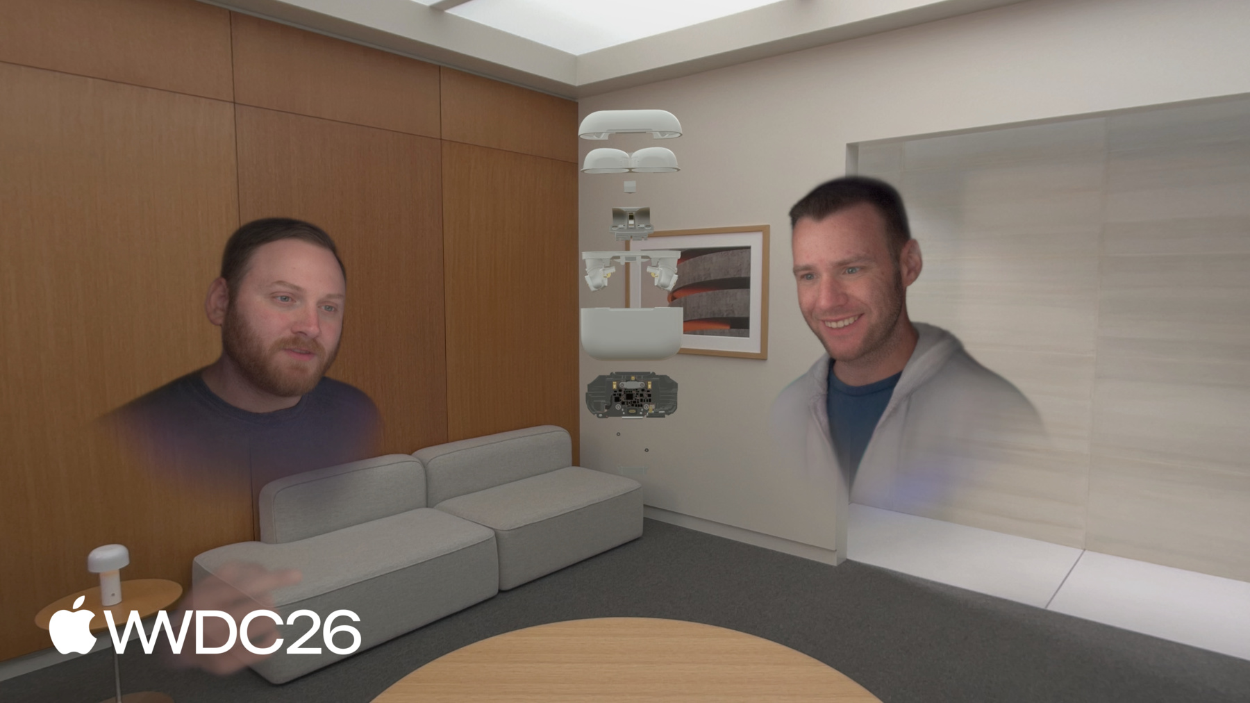
Here we see a team in a SharePlay call, a design review of the AirPods Pro. Everyone in the call sees the same asset, at the same fidelity, in the same space. The case pulls closer. It unlocks — the way it would on a workbench, except the workbench is wherever you happen to be. The bottom assembly lifts out. One person examines the interior, then rotates it so a colleague can see exactly the same thing. A point — not an annotation, not a screenshot, just a gesture toward the part that matters and the group understands.
The model collapses back. Clipping engages, a cross section opens, and the main logic board is right there — exposed in context, in a way that isn't feasible on a 2D screen.
Clipping disengages. The full assembly expands. Someone reaches in, pulls the motherboard free, and holds it up for the rest of the team. Three people, one model, and the tools they needed to understand it.
What makes all of this possible comes down to three things Apple Vision Pro does really well. Real-time collaboration: multiple people, in a shared space, at the same moment Manipulation of rich representations: because any data with enough dimensions deserves more than a flat screen.
Environment lighting: your physical world, grounding every virtual decision And those three capabilities aren't just useful for CAD. Anywhere you have complex, multidimensional information to reason about — urban planning, logistics, real estate, production design — the same principles apply. For a technical deep dive on making SharePlay work in your apps please see "Share visionOS experiences with nearby people" from WWDC25.
There are 4 major considerations in building out the sample code.
I'll start with sharing some important aspects of preparing your 3D assets so that people can easily manipulate and work with them.
Complex spatial assets are structured collections of components, organized as assemblies. I'll show you how to enable manipulating these assemblies.
Then, I'll go over clipping. That allows the insides of an assembly to become as accessible as the outside.
And finally autoexpansion, where the asset expands itself, and every sub-assembly separates and moves into position, revealing the full structure. On to asset preparation.
Assets without structure are hard to reason about and hard to use in code.
Without structure the code can't make decisions on what to hide or show, what to make manipulable.
When preparing an asset there are a lot of things to consider, what I'll focus on here is how to think about the structure of your asset, what assemblies contain what sub-assemblies. In other words the hierarchy of the model.
Some of the other considerations, of a more technical aspect, are covered elsewhere.
For details, check out "Optimize your 3D assets for spatial computing" from WWDC 24.
A 3D model is a part-whole relationship. Flatten everything to the root, and even simple operations become surprisingly painful. You've still got all the geometry — it's just not organized.
This engine block was exported without preserving its structure. Everything flattened up to the root. InteriorPart_01, InteriorPart_03, part 25, all the way down. No sub-assemblies. No grouping. And here's the thing. This asset looks completely fine in the viewport. The geometry is all there and it renders correctly. But the structure that would make it interactive? Gone. If I want to isolate one piston, it's in here somewhere. Was it InteriorPart_47 or InteriorPart_18. I don't know, and neither does my code.
Consider this updated asset, it's got a deep, nested hierarchy.
It's complex — and that's intentional.
Here we have hidden the outside of the engine and all the pistons but one. We can see a piston and the crankshaft, alone. Each one is its own node — named, organized, and grouped.
If I want to animate just the piston — isolate it, highlight it, let a person reach out and pull it free — I can. It's organized, I can write code that can find it.
That's hierarchy doing exactly what it's supposed to do. Now that we have a good hierarchy, I'll show you how to enable people to pull this hierarchy apart.
A good hierarchical structure will give people the ability to select an individual part, or move it using the natural input system on Apple Vision Pro.
This can be achieved using RealityKit's ManipulationComponent API correctly. I'll show you how this is done. Here is a demo of it in action. This is the sample app that I showed you at the beginning of this presentation. It showcases this AirPods Pro asset that I plan to use in a design review session later.
Watch what happens when we hit Open.
A moment ago, this was one object.
Now every part of it is individually interactive — grab one piece, leave the rest.
Let me show you how I got this working.
To enable people to move this assembly around, all we have to do is attach a ManipulationComponent to it. That's our starting point. Get the object manipulable so people can orient it, move it, and scale it with natural hand movements.
To learn more about ManipulationComponent see "What's new in RealityKit" from WWDC 25. To enable people to move this assembly around, all we have to do is attach a ManipulationComponent to it.
To do that we move the ManipulationComponent down to the children. Suddenly, the top enclosure can be pulled away while the bottom enclosure stays put. A collaborator can rotate one of the ear buds while someone else is examining the other at the same time. That shift, from "thing to look at" to "thing to explore," happens entirely because of where that component lives in the tree. Nothing else changed.
Once you've pulled things apart, you can move ManipulationComponent back up to the root. Now the whole spread moves as a single object again. Reposition it together, rotate it, bring one section closer — the internal relationships stay exactly as you left them.
The hierarchy hasn't changed. The geometry hasn't changed. Just where the component lives in the tree. And that's the whole idea here: component placement drives behavior. Let's look at the code to make this work. Remove the the ManipulationComponent and InputTargetComponent from the entity. That makes this entity not manipulable.
Then the code iterates the sub-entities.
Add the InputTargetComponent and the ManipulationComponent to each sub-entity.
In the sample code I make sure to set the ManipulationComponent's releaseBehavior to .stay. That makes it so the entity stays where the person puts it when they release it.
One more important note here, I'm specifically not showing the addition of the CollisionComponent. But it is critical for event processing that your entities have collision components, don't forget to add them. Of course, if you are going to open an assembly you probably want to close it too.
Closing an assembly follows the same process but in reverse.
Remove the Manipulation and InputTarget components from the sub-entities.
Add the Manipulation and InputTarget components back to the entity. That's it, the tree is now able to be manipulated as one element as if it's closed or as independent entities if it's open.
Next up is clipping. Any sufficiently complex asset has layers you can't see from the surface. The internal structure of a building, the routing behind a panel, the infrastructure beneath a city block. Clipping lets people see through the asset, literally, and it's a new RealityKit capability in visionOS 27. Let me first show you a demo of it in action, then take you through how to edit the clipping planes.
Here you will notice the assembly, unclipped sitting in space, the clipping state is .off. Then I turn clipping on and enable the clipped state of the assembly. The clipping plane is inside the assembly perpendicular to one of the primary axis, the +z vector in this case. It shows the internal structure. The clipping state is .on. Next the clipping plane moves around. That is the really cool thing I'll show you how to do.
Before we do though, let's look at ClippingComponent.
ClippingComponent has 4 properties. I'll go through the ones used in the sample code so you know what's there. bounds is the property you'll be working with most — an axis-aligned bounding box in entity local space. Anything outside it gets discarded by the renderer each frame.
shouldClipChildren defaults to false. If you add this to a parent assembly and your children aren't clipping, that's why. The sample code sets it to true.
shouldClipSelf defaults to true, which is almost always what you want. Our goal is to make the bounds editable. I'll show you how that's done after a quick look at the axis aligned bounding box. The six faces of the bounding box become six interactive plane entities — one per axis, positive and negative.
Each face here represented by a different color.
Someone grabs the +x face and pulls it to reveal more of the interior, or pushes it back out to restore it. Each plane controls exactly one scalar value in the bounds.
That's the entire interaction model. Six planes, six numbers. Keep that in mind as we work through the implementation.
To manage clipping we have a three-state machine. Clipping can be .off — the assembly is not clipped. When clipping is .on the model is clipped according to the bounding box, In the .editing state clipping planes are visible and interactive. People can change the clipping bounds by moving them. Let's look at it in action.
In the .off state there is no clipping of the assembly, only the outside of the assembly is visible.
In the .on state clipping is active and shows the inner workings and layout of the sub-assemblies.
In .editing state, clipping planes are on and people are able to move the planes. As the planes move the clipping bounds are changed and more or less of the internal layout of the model becomes visible. Let's look at the technical details that make this all work.
There are three components involved. In the off state we have the ClippingBoundsCache, a custom component in the sample code. It keeps track of the clipping bounds that were last edited and provides that value to the ClippingComponent when the state switches to .on. In the .on state the ClippingComponent is created and added to the entity. This is the RealityKit component we discussed earlier. Geometry that's outside its bounds is discarded.
In .editing we add another custom component called ClippingTransformSync, the sample uses that to keep track of the assemblies transform and update the ClippingControl when the transform changes. The ClippingControl is the entity we use to manage the clipping planes and make them interactive. They are the visual affordance that allow people to see where the clipping planes are and edit them. There are four coordinate frames involved. The first is the world coordinate system, it's where everything else sits.
Model is where the model lives, and is the coordinate frame the clipping component operates in. Changes to the bounds need to be made in this frame.
The clipping control frame is where we put the editing planes that allow people to change the ClippingComponent's bounding box. The clipping plane coordinate frame is where the editing planes live and where the drag gesture events are expressed. Changes to the position of the planes need to be in this frame and constrained to move in a direction expressed in the model frame.
World has two children. The Clipping Control and Model Clipping Control contains the editing planes And Clipping Plane is the coordinate frame where the drag gestures are expressed. The task is to get the change in drag gesture expressed in the Model frame constrained then converted back to the Clipping Plane.
To this point we've been talking about the clipping as a monolithic thing, but there are two distinct parts that are worth separating. The ClippingComponent is in the model's coordinate space so to edit these bounds we need to have the change expressed and constrained in that coordinate frame.
The visual planes provided a visual understanding of what the movements do. The planes need to move with the events as well, but they are expressed in the clipping plane coordinate system, so updates to their positions need to be expressed in their coordinate frame. In both frames the change needs to be constrained to the direction normal to the bounding box plane. Let me show you how all this fits together.
There are 4 distinct steps from the drag gesture to updates for the bounds and plane position. I add a drag gesture to the clipping planes, one for each plane. Again, this is the coordinate frame the events arrive in. I transform that into the World coordinate frame.
From there, I transform to the Model frame. Then I constrain the delta to the appropriate direction — +x, -y, etcetera — depending on which plane the person is moving.
Now I have the value I need, in the coordinate frame I need, constrained to the correct direction, and can update the clipping bounds. To update the plane's location I'll have to convert this vector to the plane's coordinate frame. We'll look at that in just a second. For more information about the gesture component check out "Better Together: SwiftUI and RealityKit" from WWDC 25.
With the big picture in mind, let's look at each step in detail.
The gesture is expressed in the Clipping Plane coordinate frame. It will look something like this. The drag delta has values 0.5, -0.75, and 0.1. These values are the expression of the drag delta in the Clipping Plane coordinate frame. The task is to change the expression of this vector to the Model coordinate frame.
The drag delta vector is transformed from the Clipping Plane coordinate frame into the World coordinate frame. Keep in mind, the vector hasn't changed, only the coordinate frame the vector is represented in. Since Clipping Plane and World are not the same coordinate frame, the numbers change. It's the same vector, just a different representation.
Before we can update the clipping bounds, the drag delta vector must be in the Model coordinate frame. So, we do one more transform from the World coordinate frame into the Model coordinate frame. Again, the vector hasn't changed, just the coordinate frame it is represented in.
Now comes the mathematical magic. We project the drag delta onto the proper direction, which is just a fancy math way to say how long the drag delta is in the direction we care about. Let's remove the AirPods Pro case so we can see the process better. Projection sounds complex, but it really is just how long is the drag delta along the direction we care about.
It's like measuring the shadow of the drag delta vector cast on the direction vector.
Here is the math equation, don't let it scare you. I'll break it down piece by piece. First it's finding a vector in the direction we care about.
You might have done this before, it's the vector dived by its length squared.
In our case this is simple, the direction we care about is the normal to the plane, +x here, or {1, 0, 0}.
Then we do a dot product, which is a type of vector multiplication, with the drag delta and the direction vector. That gives us the amount we want the bounding box to change, but it's just a number, we also need the direction. So we multiply the direction we care about, the normal to the plane, by the amount we found in the last step. Now I have the constrained delta in the Model coordinate frame. That is exactly what I need to updated the bounding box of the ClippingComponent.
Here is the assembly clipped, the inside is as visible as the outside. That's pretty cool.
Now, I go through the same constraint process. But this time to the Clipping Plane coordinate frame.
We have to transform the constrained drag delta from the Model coordinate frame into the Clipping Plane coordinate frame then we project that down onto the plane's normal, the same way we did last time. This gives us the value we need to move the plane. But, since it's been projected onto the normal the change is constrained to move only in that direction, instead of where ever the person moved their hand. That makes sure the changes from the gesture feel natural.
Here we see the planes turned on and waiting for people to interact. We keep them on in the .editing state so that people know they can reach out and move any one of these six planes.
6 planes, 4 coordinate frames. Simple transformations between each makes the individual calculations easier to reason about.
Once you have the hierarchy of the coordinate systems in mind and the really cool math trick of projection, you can make this interaction feel natural in your apps. Now, let's talk about automatic expansion of the sub-assemblies that make up a 3D model. People use this to reveal the model's inner structure. This feature can be great for a mechanical assembly, a building, really any asset where understanding how the parts relate to the whole would be helpful. I want the model to expand in an intuitive way. But I don't want to force the person to choose that direction. We are going to use a bit of math so the code can make the decision. I'll walk you through that, and show you exactly how it works.
When an assembly loads, its children sit exactly where they are defined in the file.
For a well-constructed asset that means they're probably overlapping — nested inside each other the way they exist in the real object. That's correct, but it's not useful for exploration.
Expansion fans the children apart along a single axis, giving each one space to be seen and grabbed independently.
One tap, the assembly opens itself. The process of doing that is not complicated, let's look at it a piece at a time.
We could display the assembly spread along the x-axis, like this. It does capture the idea of the pieces pulling apart in space to expose the interior layout.
But, we'd like the expansion to feel more natural. More like what a person would expect in a design review.
And have it expand along the y-axis like this. The question is, how does the code choose which axis to expand along? For that I'll take a brief diversion into two concepts: variance and weighting.
A low variance is just a way to say all the values we have are basically in the same spot.
For example, in this dartboard diagram the values are anything, like ice cream sales to incidence of sunburn. It's just a way to get across the idea that values, whatever values, are close together.
A high variance will have the values spread out.
Now that we have a feel for variance, let's look at it a little closer.
I'll move to one dimension to make things a little clearer. Again these values are just numbers, they could represent anything, the frequency of 6 guitar strings, or anything else that has a single value per sample. Each of our points is placed on a number line along with an indicator of how far the value is from the average.
The distance from average is called deviation. This is the first step in finding the variance.
Next, is to square each of the deviation values then add them together, and divide by the count to find the average. That's the variance. It's simple enough math, the technical terms "variance" and "deviation" is usually what gets people. Conceptually, it's just a way to numerically specify how much our set of values is spread out from the average.
Now consider, some of these values might be more important than others.
That's where weighting comes in. We use it to distinguish the importance of individual values.
Each of the points now has a radius to represent a weight factor, the larger the circle the more important the value.
The weighting factor could be anything, saturation of a gradient, or any other value that expresses importance. We are staying abstract to illustrate the process. We use the weight, or importance, to calculate a weighted variance. In addition to squaring the deviation values we multiply each by its weight.
And boom, now we have a weighted variance. With the weight, each value can have a different importance. And that's exactly what we'll do to figure out what axis to expand our assembly along. We'll calculate the "volume-weighted position variance", what a mouthful, along each axis and expand along the axis with the largest variance.
Here, notice the table: one row for each of the sub-assemblies. It shows their volumes, and their positions.
These are the values I'll use to find the natural axis to expand along. I'll use the x, y, and z values to calculate the variance in each direction.
The dots are sized to reflect the volume of each element. I'll use the volume as the weighting factor.
Here is the volume-weighted variance for the x axis. Most of the sub-assemblies lie at or very near the same position along the x axis. That leaves us with a small variance along x. Since most of the sub-assemblies are at or near each other the volume weighting factor doesn't make a difference along the x axis. The two ear buds are spread out on the x axis and do their best to contribute, but there volume is not enough to make up for all the other elements at the same place.
The result along the z axis is even smaller. The Bottom insert does have some volume to weight its contribution, but it's too close to the average position to make much of a dent. The Hinge and Lid retention magnet have too small of a volume to pull the variance very far.
This takes us to the y axis, the clear winner here. The large parts are further away along the y axis and the larger volume provides weight to their distance.
With y being the clear winner we assemble a set of FromToBy animations to move the sub-assemblies into position along the y axis.
And there we have it, the interior of the model exposed for people to interact with. There is a lot I've covered today from showing you how to prepare an asset hierarchy, manipulate its parts, use a clipping plane to look through a complex assembly, and even expand the parts out along an axis to give you a detailed view of the tiniest part of your assembly.
This workflow can help you build design review apps that can greatly enhance people's productivity.
Download and explore the sample project from developer.apple.com I'd highly encourage you to familiarize yourself with concepts in statistics, vector math, and linear algebra. Those are the parts of math we leaned heavily on today, hopefully you find them a little less scary now than you did before.
If you'd like to control models in real time from your Mac app, the spatial preview framework might be a great choice for you.
Do check out the session "Discover the spatial preview framework" to learn more. Additionally, you could even augment a physical object like a race car simulator cockpit and overlay your virtual content on top of the simulator and explore its internal structure with what you learned in this session.
To learn more about augmenting physical objects please check out the "Explore enhancements to visionOS object tracking" session.
Thanks again for your attention today and I look forward to seeing the cool stuff you do with these ideas in your apps.
-
-
7:10 - Opening an assembly
func openAssembly() { components[ManipulationComponent.self] = nil components[InputTargetComponent.self] = nil for child in assemblyChildren { child.components.set(InputTargetComponent()) var manipulation = ManipulationComponent() manipulation.releaseBehavior = .stay child.manipulationComponent = manipulation } } -
7:11 - Closing an assembly
func closeAssembly() {
    for child in assemblyChildren {
        child.manipulationComponent = nil
        child.components[InputTargetComponent.self] = nil
    }

    components.set(InputTargetComponent())
    var manipulation = ManipulationComponent()
    manipulation.releaseBehavior = .stay
    manipulationComponent = manipulation
}
-
-
- 0:00 - Introduction
An overview of building collaborative spatial experiences on Apple Vision Pro, including real-time manipulation of rich 3D assemblies, interactive clipping, and automatic expansion of sub-assemblies.
- 2:55 - Asset preparation
Learn the key requirements for preparing 3D assets for spatial computing, including preserving a deep, nested hierarchy in your USDZ exports so that individual parts remain independently selectable and manipulable at runtime.
- 5:05 - Manipulating the hierarchy
See how to use ManipulationComponent and InputTargetComponent to make an entire assembly — or each of its sub-entities individually — interactive. Covers the openAssembly() and closeAssembly() patterns and the releaseBehavior setting.
- 8:15 - Interactive clipping
Explore ClippingComponent, a new RealityKit capability in visionOS 26 that lets people see through complex assemblies. Covers the three-state clipping machine (.off, .on, .editing), coordinate frame transformations, and how drag gestures update clipping plane bounds.
- 18:16 - Autoexpansion
Understand how to automatically expand an assembly's sub-components along the most meaningful axis using volume-weighted variance. Covers the math behind choosing the expansion axis and assembling FromToBy animations to move parts into position.
- 24:10 - Next steps
Key takeaways and pointers to the Model Manipulator sample project, related sessions on the spatial preview framework, and recommended background on vector math and linear algebra.